Sensor Technology
Though our technology has its origin in microelectronics our fabrication process differs substantially from microelectronics standards. Purity reasons, the demand for a fully doublesided process as well as large detector surfaces are the main causes making our fabrication process neither adaptable nor directly transferable into a conventional microelectronics process unit.
MPG HLL technology provides:
- 6 inch wafer processing for full depletion at low voltages , 8 inch compatible
- Homogeneous ultrathin radiation entrance window – soft X-rays, UV sensitivity
(Double sided processing without contact to sensitive area, dead layer of <30nm) - Large sensitive area
(Wafer scale devices, large unperturbed fields of view) - Low noise, excellent energy resolution
(Low leakage current process (< 10 pA/cm2 @ RT and 450 μm depletion) - High speed with low noise and long term stability and high SNR
(Monolithically integrated first amplifier in the sensor.) - Low material budget sensors and modules
low multiple scattering in tracking systems, low background for electron detectors
(Thinning technology on SOI structures with all silicon module concept) - Compact systems with high number of readout channels
(Wafer/device interconnection technologies compatible with sensor technology)
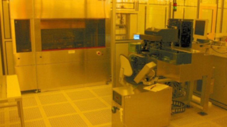
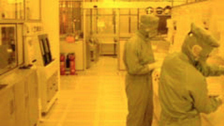
We are in the unique position to have a production line which combines processes for ultra-pure silicon wafers with the small-scale technology of very large system integration (VLSI) electronics. The complete processing is done exclusively in our 1,000 square meter cleanroom.
Short movie about the equipment and processes at MPG HLL can be found here : link
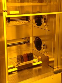
The starting material for wafer production is detector grade float zone silicon of high resistivity with a diameter of 150 mm and a thickness of 450 μm. At the beginning of processing a thin oxide layer is grown on the surface of the silicon wafer. The quality of this oxide defines the boundary of the silicon crystal and many properties of MOS structures. The cleanliness of this very first processing step has also a strong influence on the final detectors.
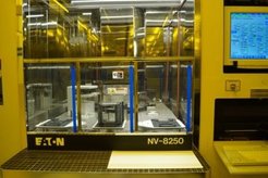
Ion implantation is used to define pn-junctions and to shape the electric potential inside the wafer. The potential defines the single electron’s path inside the silicon volume and (via Ramo‘s Theorem) the induced signal at the readout nodes. The shape of the implant depends on multiple factors. It’s peak dose can have depth from several nanometers up to several micrometers and depends mostly on the energy used for the implantation.
While the depth of the implant is controlled by ion energy, the lateral extend is defined by masking with photoresist. The photoresist is spun on the wafer surface and then exposed to UV-light making the resist dissolvable in a developer solution. The exposure is done either through a mask by means of proximity projection, or with a direct writing laser system. Despite its slower speed, direct writing of the design data with the laser is usually preferred as it allows smaller feature sizes down to 1 μm and faster design changes. The use of projection lithography (wafer stepper) is prohibited by the large dimension of the sensors. After photolithography, the pattern can also be transferred into the layer on which the resist is coated by wet chemical etching.
Insulating and Conductive Layers
We use different dielectrics as insulating layers. These thin layers with thicknesses between several nanometers and some micrometers thick, are deposited in a furnace by low-pressure chemical vapor deposition (LPCVD) or plasma enhanced chemical vapor deposition (PECVD). Polysilicon is also deposited in the LPCVD furnace. It is used as conductor withstanding much higher temperature during later processing steps but not offering the same low resistivity as aluminum. In addition, polysilicon can be covered with a self-aligned isolator that is grown from the silicon by wet oxidation in water vapor. Aluminum is used as a conductor between silicon and the outside world. Aluminum is deposited by sputtering off a high purity aluminum plate and forming a low resistive ohmic contact. The sputtering process creates also radiation damage in the silicon bulk which can be healed by consecutive tempering. Currently our technology offers a maximum of two polysilicon and two aluminum layers per side. For the DEPFET active pixel sensors (see link ) – all four layers are necessary. Additional metal layer available at MPG HLL is Coper. It is used as final metal layer when interconnection via bump bonding is needed for the project and serves also as redistribution layer.
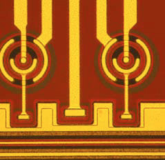
Before the wafers have left the cleanroom area, a passivation layer made of synthetic material is applied for easy mounting and reduced sensitivity to particles. The plastic is spun like photoresist and is photosensitive so that it can be selectively hardened by UV-exposure. The passivation layer as well as the whole sensor has been tested to withstand temperatures between liquid nitrogen and several hundred degrees Celsius.
Inline Control Quality Management
All process steps from selecting wafer material to final cleaning on wafer level are constantly checked and documented. We use detailed machine logging, a wafer database and several analysis methods (REM, SIMS, VPD, various electrical tests, control of air and water purification) to ensure quality. Another challenging effort is to inspect all lithographic and structuring steps by microscope. We are screening the whole wafer surface to find lithographic artefacts and defects. Although we have established several methods to repair some of them, sometimes complete lithography steps have to be repeated. Only such a kind of high inspection effort is ensuring a high yield through many processing steps with extremely large devices up to 100 cm².
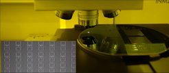
Electrical Wafer-Level Testing
Intensive inline and offline electrical testing is performed at wafer level. Electrical contacts, insulator properties and resistor values are measured. Device parameters like leakage currents, flatband shift or depletion voltages are determined. After the full characterisation of the devices on the probe stations mounting and bonding is performed.
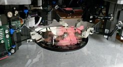
After measurements on wafer level we separate the wafer into chips. The diced chips are cleaned and mounted on dedicated ceramic carriers. The mounted chips are bonded by an automatic or manual bonding tool. Wafer bonding techniques as well as flip-chip processes are very well established at MPG HLL (see link).

Right: BELLE II PXD module developed for the accelerator at KEK Japan


